Introduction
BRE Global has been awarded a contract by the Department for Communities and Local Government (DCLG) to continue fire investigation activities on behalf of DCLG until 2015.
An important element of this contract is to ensure that findings from fire investigations are made available to the fire community, and other stakeholders.
Background
Along with many other countries in the world, the UK is seeking to increase the proportion of energy that is obtained from 'renewable' sources, such as those that exploit wind, biomass or solar energy.
One of the most popular, in particular in the domestic market, is production of electricity from solar energy using photovoltaic panels, and, encouraged by government incentives, the numbers of these systems in use has rapidly grown in recent years.
All new technologies can introduce new risks, and all new energy-handling systems can introduce new fire risks. Evidence is emerging from Europe and North America of the potential for fire hazards associated, directly or indirectly, with renewable energy power generating systems such as photovoltaics and wind turbines. Fires involving these systems can present some unique challenges for the fire service, building occupiers and insurers. See, for example, Grant (2010) and CFPA (2012).
Objective
The aim of this article is to provide a summary of the known or potential safety hazards from fires due to, or involving photovoltaic (PV) systems. Also explained are the issues fires in such systems can present in terms of fire-fighting and the impact on the building occupants.
This article is intended to raise awareness of the emerging issues and thereby be of assistance to the fire and rescue services, insurers, planners, architects, designers, building owners and fire risk assessors, as well as interested parties within the PV industry; designers, manufacturers, installers and maintainers.

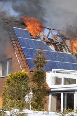
Figure 1 - A fire involving PV panels (Photograph courtesy of Bodo Wolters)
Scope
At the present time there is no reason to believe that the fire risks associated with PVs are any greater than those associated with other electrical equipment. Nevertheless these systems are now more common - recently, there has been rapid growth in the market - hence it is important that any risks associated with such installations are more widely appreciated.
In contrast to the power used by conventional mains electrical equipment, the power that PV systems generate is DC (direct current) and parts of the systems cannot be switched off. DC installations have a continuous current, making them more hazardous (volt for volt) than normal AC (alternating current) electrical installations where the voltage and current oscillate. This can affect the muscles of the human body differently; DC current will continuously contract the affected muscles making it difficult to break contact with live components; AC current provides an opportunity for release as the current reverses its direction.
Fires involving renewable energy technologies are quite rare but incidents involving PV systems are being reported. Although actual numbers of fire incidents involving PV systems are not known, in the last two years BRE has been notified of eight incidents which were of concern to local Fire and Rescue Services.
This article only discusses the identified fire risks during operation; it does not cover any fire risks that may be present during the PV system installation although there may be some overlap.
Renewable energy technologies generally, and PV systems in particular, are rapidly developing and innovative systems are continually being introduced so this article provides only a very brief and simplified 'snap-shot' of the situation at the time of writing.
What is a PV system?
Photovoltaic (PV) panels (also called solar electric panels) convert energy from the sun into electricity. PV panels (or modules as they are sometimes called) are composed of a number of PV cells (or solar cells) containing a photovoltaic material (Pester & Thorne, 2011), and these can be in a variety of shapes and sizes. There are a number of photovoltaic materials currently in use, and the technology is rapidly evolving. For building applications, a number of PV panels are normally connected together to form a PV array, and most panels are currently being fitted to existing roofs using external framework. However, there is a variety of more specialised panels designed to form part of the building covering, for example building integrated panels, solar tiles and glass facade components are available. These products are collectively known as Building-Integrated PV - BIPV (Pester, 2012).
Photovoltaic panels generate electrical power by converting solar radiation into direct current (DC) electricity by utilising the photovoltaic effect within specialist semiconductor materials. PVs will work, to some extent, in any weather as long as there is daylight and so can still generate some electricity on a cloudy day.
The power, which is measured in watts (W), can be used on site or routed back into the electrical grid. PV panels are rated in watts-peak (Wp) and arrays in kilowatts-peak (kWp). A typical domestic system would be rated at 2-4 kWp, whereas commercial roof-mounted systems can be from domestic size up to 1000 kWp for very large area roofs. Large ground-mounted PV arrays (solar farms) can generate many megawatts (MW), and sizes are increasing all the time.
In general, a building-mounted PV installation comprises the following:
- The PV panels, affixed to the roof of the building or integral with the roof or facade.
- DC cables, connectors and junction boxes which take the power produced to an inverter. Sometimes junction boxes can also contain fuses, diodes and surge-arrestors.
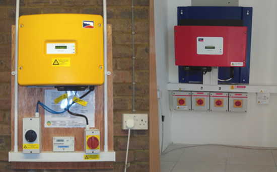
- One or more inverters which convert the DC power to AC (see Figure 2). These are often termed 'string inverters' or 'central inverters'. The majority of installations in the UK use string inverters.
- 'Micro-inverters' involve an inverter, usually mounted on the roof under each panel, or small group of panels, which reduces the length of DC cabling and avoids high DC voltages, which are a potential source of electrical arcs. The remaining cabling on the roof and down to the distribution board can then be standard AC cable (exterior grade on the roof). The use of micro-inverters is becoming more popular as more systems come onto the market.
- One or more DC isolation switches provided to isolate the PV array from the inverter (see Figure 2). Note that DC isolation switches are not interchangeable with AC isolation switches.
- AC cables which take the AC output from the inverter to the building's main electrical supply. There will be a meter to record the energy generated and an AC isolation switch on this line.
- A connection to the main AC supply via suitable protection devices, such as circuit breakers and residual current detectors (MCBs and RCDs).
- Alternatively, for off-grid premises or installations, the DC power may be stored in batteries and/or converted to a local AC supply.

Figure 2 - Typical domestic inverters. The image on the left shows two isolation switches, DC on the left and AC on the right.
Standards and Codes
PV installations should be installed in accordance with national guidance (MCS, 2012) and any specific guidance issued by manufacturers. There are a number of standards that PV products should comply with (BS EN 61730-1, BS EN 61215, BS EN 61646, MCS 0065) which include (amongst other factors) requirements that address fire hazards.
Where the system owner wishes to register to receive the government's feed-in tariff incentive, PV installations of less than 50 kWp must comply with the MCS (microgeneration certification scheme) installation standard MIS 3002. To comply with MIS 3002, installers must use MCS (MCS 005 and Microgeneration Certification Scheme) or equivalent certificated PV modules. MCS certification of PV modules requires testing of products to international standards and assessment of manufacturing processes, materials, procedures and staff training. It therefore provides building owners with a measure of confidence in the installers and products used. Furthermore, PV systems that form part of the roof structure should satisfy a fire exposure test, e.g. DD CEN/TS 1187 test 4 or BS 476-3. This test seeks to ensure that fire will not spread between buildings via the roofs. From April 2014, all systems mounted on pitched roofs must also comply with MCS 012 in order to be accepted under the MCS. MCS 012 includes wind uplift and weather tightness testing of pitched roof installation kits and, for roof integrated products, the fire exposure tests described above.
Fire safety issues
All electrical installations, by their nature, will carry some degree of fire risk. Although fires caused by PV panels are rare, any fire involving a building with a PV array can present an increased risk to occupants and fire-fighters.
PV arrays with string or central inverters involve DC at elevated voltages and it is not normally possible to completely isolate the DC electrics between the PV array and the DC isolation switch. Additionally, PV modules are current-limiting devices meaning fuses are not likely to operate under short-circuit conditions which could mean a fault in the system goes undetected. This scenario can present fire and/or electric shock risks, although these can be minimised by good system design, product selection and installation practices.
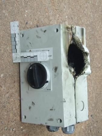
In fires that BRE has been informed of where the PV systems have been the cause of the fire, these fires have generally resulted from poor installation or the use of wrongly specified, incorrect or faulty equipment. Specifically, there have been reports of installations of AC isolator switches being used mistakenly in DC circuits resulting in a build-up of heat within the switch enclosure and leading to a fire (see Figure 3). Other incidents have resulted from the use of faulty inverters or faulty DC switches or the absence of isolator switches. Any switching or connection faults on the DC side of a system can result in the generation of a high temperature arc or high resistance fault which could start a fire. DC arcs can be difficult to extinguish and pose a risk to fire-fighters attempting to suppress the fire.

Figure 3 - Damage to a DC isolation switch caused by fire within the switch (Photograph courtesy of Devon & Somerset Fire & Rescue Service Fire Investigation Team)
Current MCS guidance (MCS, 2012) for the installation of PV systems recognises the potential risks from fire and includes some recommendations for prevention/mitigation of these risks, although further guidance is a topic still under discussion within MCS. Clearly good design and proper routine testing, servicing and maintenance are essential for risk management.
In the event of a failure of the AC supply to a building, (for example due to a local power cut, or a fire) the inverters are designed to shut down automatically. However, the solar DC supply (from panels to the DC isolator) will still be live during daylight. It may therefore still be necessary to manually isolate the DC cables and components from the PV panels which will otherwise remain live.
If a fire damages the DC cables from the PV array, for example by burning off insulation, then there will be risk of electric shock from the exposed DC conductors, in particular to fire-fighters.
Poorly installed panels may obstruct or restrict use of roof windows as means of escape.
Concerns have been raised regarding the presence of heavy metals within some specific types of PV cells, and whether such metals can be or are released during a fire (e.g. PV Thin). Therefore, while such risks are considered to be low, caution is needed, as with any fire involving electronic elements, in dealing with fire damaged components and residues since a variety of heavy metals and other toxins may be present.
Many PV systems feed energy into the electricity grid at times when it is not required by the building. Reports are now indicating that, where such a feed in is occurring from a number of distributed sources, this can cause voltage fluctuations in the grid. Fluctuations are known to have the potential to cause fires in sensitive equipment, such as television sets (e.g. Bach, 2012; Hepworth, 2011; Tozer, 2010).
Fire-fighting issues
There is currently no national UK guidance specific to fighting fires involving PV systems. In most respects, fires involving photovoltaics are little different from any fire involving live electrics, however, PV systems do present some new risks to fire-fighters:
- Fire-fighters may not recognise a PV system and few know what to expect; there are a large number of different types of PV systems available and, in commercial buildings, these may be hidden on flat roofs. The new MCS installation guide (MCS, 2012) requires that a fire-fighter's label be affixed in a prominent place close to the electrical shut-off point.
- Fire-fighters are not used to dealing with DC in buildings, although they have considerable experience in dealing with vehicle electrics (which are DC). There are potentially very high DC voltages (up to 1000 V DC in large installations) which are more dangerous than car electrics and normal (AC) electrical installations.
- Parts of the system are always live while light falls on the panels (artificial lighting may generate small currents). Unless micro-inverters, or remotely controlled safety devices are used at panel level, it is only possible to shut off the building's AC system, not the supply to the DC isolator. o It is reported that fire-fighters in the USA are using portable covers for the PV panels in order to shut off the light supply and so prevent the generation of electricity by the panels. Heavy, densely woven fabric and dark plastic films can be effective in reducing the power to near zero, but care must be taken to ensure no light can get through the cover (Backstrom & Dini, 2011).
- If the structure is metal or steel frame, then an accidental short may result in parts of the building being 'live'.
- There is the risk of electric shock if cables are cut or become damaged by fire. This includes cables from battery banks where these are used to store generated electricity.
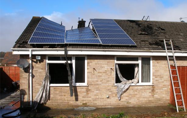
- Should the roof of the building be affected by fire, then the additional mechanical loading due to the weight of PV panels, or additional wind-loading caused by the panels, may cause early collapse of the roof (see Figure 4).
- It is also possible that arrays which are stood off from the roof may cause a channelling effect, thus exacerbating a fire affecting the roof.
- There is the risk that panels, or glass from the panels, may break and fall onto personnel below.
- The panels can get hot (from the sun) with a (minor) risk of burns.

Figure 4 - Image of potential roof collapse due to additional loading (Photograph courtesy of Adam Course, Avon & Somerset Fire & Rescue Service)
Noting that large building-mounted PV arrays may generate up to 1000 V DC, a particular risk to fire-fighters, and identified overseas but without verified evidence, is the limited potential for electric shock from current being conducted down a fire-fighting water jet or if they cut through PV panels as part of their strategy to vent the fire.
It is the case that the presence of panels on a roof will limit the opportunities for venting smoke and fire, should it be required. Fire crews have also reported difficulties in fighting fires from aerial platforms with PV panels on the roof. During one particular incident, the PV panels remained in place on the roof when the rest of the roof underneath had collapsed and the panels deflected the water being applied from the aerial platform (anon, 2012). Since panels may be slippery, this will be a hazard for fire-fighters working on the roof of a building and may limit access to and the use of a roof. In general, panels should not be used as walkways, unless there is confirmation that they have been designed to take the mechanical load.
All MCS and best practice-compliant building-mounted PV installations with string or central inverters include at least one DC isolation switch, capable of breaking both positive and negative connections under full load, mounted close to the inverter. Often, where there is a long run of cable between the array and the inverter, a second isolator may be used. Where micro-inverters are fitted, there may be no DC isolation switches as the majority of the cabling is AC.
Inverters (and DC isolation switches) are often installed on the top floor of the building, or on/under the roof. This is not likely to be readily accessible to fire-fighters tackling a fire in the building. New products are becoming available which allow the DC switch to be operated remotely, for example from the main electrical unit at ground floor level. These are sometimes known as 'fire-fighter's switches'.
Sources of guidance
Current UK guidance for fire-fighters is included within general guidance on fighting building fires although, and while PVs are explicitly mentioned, there is currently no specific advice provided (DCLG, 2011).
A guidance document by the British Photovoltaic Association (BPVA, 2011) is available, but this document appears to be under development.
Two useful guidance documents have been produced in the USA (Grant, 2010; Backstrom & Dini, 2011); the latter describes some experimental research primarily regarding fire-fighting concerns, including distances from PV systems when applying water; the former guide identifies a number of causes of fire similar to those described within this article.
The German Fire Service Association has produced guidance for fire-fighters (e.g. Haselhuhn, 2011) which provides advice on how to approach a building with PVs and guidance on how far away fire-fighters should stay from electrical installations when applying water onto a fire.
The German guidance regarding distances is not specific to PV installations but is for all electrical installations. It recommends distances of between 1 and 5 m depending upon the type of water jet being used and likely voltages present. The guidance from the USA, however, specifically addresses distances from PV systems and recommends similar distances to those of the German guidance, i.e. between 1.5 and 6 m, again dependent upon the type of jet used and likely voltages encountered.
Conclusions
At the present time there is no reason to believe that the fire risks associated with PVs are any greater than those associated with any other electrical equipment. But, as with all electrical equipment, it is important that these systems are correctly designed, consist of properly tested components, are competently installed and are regularly maintained.
For the fire and rescue services, there is a need to formulate appropriate and sound operational guidance (see, for example, Merseyside FRS, 2012; Smith, 2013; Kent FRS, Jan & Feb 2013). In recognition of the need for the PV industry to work with UK fire and rescue services to develop better guidance, on 1 May 2013, MCS (administered by Gemserv on behalf of the Department of Energy and Climate Change (DECC)) organised a workshop with representatives of a number of fire and rescue services and private fire investigators which focussed on fire safety and solar photovoltaic (PV) installations (MCS, 2013). It is intended that the findings from this workshop will form a contribution to the next generation of guidance.
It is intended that this article will raise awareness of the emerging issues and, without causing undue concerns, put the risks into perspective by providing useful information to help avoid or minimise the likelihood of an incident, or in the event of an incident, the information presented here may contribute to the fast and effective management of the situation.
Acknowledgements
Thanks go to Bodo Wolters (FMGlobal), Devon & Somerset Fire & Rescue Service Fire Investigation Team, and Adam Course (Avon Fire & Rescue Service).
The research on which this article is based was commissioned by the Department for Communities and Local Government (DCLG) and carried out by BRE. Any views expressed are not necessarily those of DCLG, with whose permission the article is published.
Martin Shipp is Technical Development Director, Fire Safety. David Crowder is Business Group Manager for Fire Investigation. Ciara Holland is a Fire Investigator. Steve Pester is a Principal Consultant, Building Futures Group, specialising in solar energy. John Holden is Principal Consultant, BRE Global MCS (microgeneration certification scheme) Team.
BRE staff have carried out fire investigations in support of building regulations (and its precursors) on an ad hoc basis since 1948, and with a dedicated team since 1974. BRE has been wholly owned by the BRE Trust since its privatisation in 1997. BRE's fire investigation team is independent and provides world class fire investigation services to a wide range of clients, including insurers, legal firms, fire and rescue services, police and government departments.
References
Annabel Hepworth, Rooftop solar panels overloading electricity grid", 13 October 2011.
Anon., "Fire at Toad Hall Nursery in Woking disrupts children", 13 December 2012.
British Photovoltaic Association. Photovoltaic's and fire: A guide from the BPVA, BPVA, 2011.
BS 476-3:2004. Fire tests on building materials and structures. Classification and method of test for external fire exposure to roofs.
BS EN 61215:2005 Crystalline silicon terrestrial photovoltaic (PV) modules. Design qualification and type approval.
BS EN 61646:2008 Thin-film terrestrial photovoltaic (PV) modules. Design qualification and type approval.
BS EN 61730-1:2007+A2:2013 Photovoltaic (PV) module safety qualification. Requirements for construction.
Casey C. Grant, Fire fighter safety and emergency response for solar power systems. Final report, Fire Protection Research Foundation. USA, May 2010.
CFPA-E No 22:2012 F European guideline: Wind turbines fire protection guideline, CFPA Europe.
DD CEN/TS 1187:2012 Test methods for external fire exposure to roofs.
Department for Communities and Local Government, Chief Fire & Rescue Advisor, Generic Risk Assessment 3.1: Fighting fires in buildings. Volume 3, The Stationery Office, 24 March 2011.
James Tozer, "Dozens of TVs and fridges catch fire after theft of £20 cable triggers massive power surge", 4 May 2010.
Kent Fire & Rescue Service Operational Guidance, Standard operating procedure. Fires involving photovoltaic & solar thermal installations, Issue 1.0, February 2013.
Kent Fire & Rescue Service, Risk assessment: Electrical installations. Fires involving photovoltaic and solar thermal installations, V1.0, 14 January 2013.
MCS 005 Product certification scheme requirements: Solar photovoltaic modules. Issue 2.3. Department of Energy and Climate Change (DECC), February 2009.
MCS 012 Product certification scheme requirements: Pitched roof installation kits. Issue 1.1. Department of Energy and Climate Change (DECC), 21 June 2013.
MCS, Guide to the installation of photovoltaic systems, 2012.
MCS. PV installations and fire safety event, 12 March 2013.
Merseyside Fire & Rescue Service, Service instruction 0764: Photovoltaic (solar) panels. Private communication from R. Pritchard, Merseyside Fire & Rescue Service, 22 December 2012.
MIS 3002 Requirements for contractors undertaking the supply, design, installation, set to work commissioning and handover of solar photovoltaic (PV) microgeneration systems. Department of Energy and Climate Change (DECC), Issue 3.1, 22 February 2013.
Paul-Frederik Bach, "German power grids increasingly strained", 1 June 2012.
PV Thin, "Is there a risk from thin-film modules involved in a fire?", (undated).
Ralf Haselhuhn, "Planning and constructing PV systems in line with fire safety regulations" ep Photovoltaik International, 2011 pp48-53.
Robert Backstrom and David A. Dini, Firefighter Safety and Photovoltaic Installations Research Project. Underwriters Laboratories Inc. USA, 29 November 2011.
S. Smith, "Solar panels fire risk". International Fire Professional, Issue 4, April 2013.
Steve Pester and Andrew Thorne, Photovoltaic systems on dwellings; key factors for successful installations. BRE Information Paper IP 8/11, 2011.
Steve Pester, Building integrated photovoltaic systems. BRE Information Paper IP 11/12, 2012.
The Microgeneration Certification Scheme (MCS).
About this article
This article was first published in International Fire Professional, Issue No 6, October 2013. It has been slightly reformatted here.


